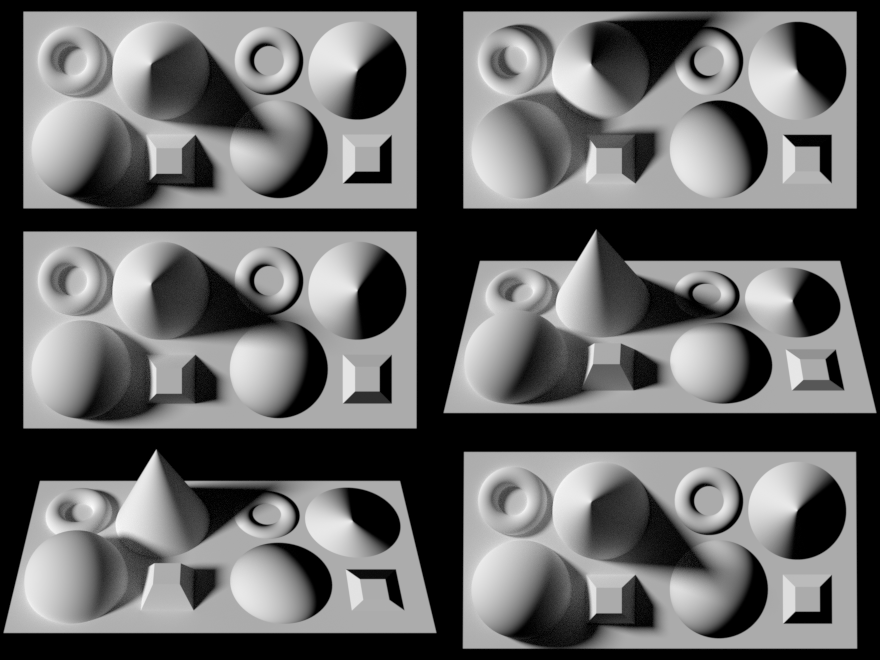
In 3D computer graphics, normal mapping, or Dot3 bump mapping, is a technique used for faking the lighting of bumps and dents – an implementation of bump mapping. It is used to add details without using more polygons. A common use of this technique is to greatly enhance the appearance and details of a low polygon model by generating a normal map from a high polygon model or height map.
Normal maps are commonly stored as regular RGB images where the RGB components correspond to the X, Y, and Z coordinates, respectively, of the surface normal.
History
The idea of taking geometric details from a high polygon model was introduced in “Fitting Smooth Surfaces to Dense Polygon Meshes” by Krishnamurthy and Levoy, Proc. SIGGRAPH 1996, where this approach was used for creating displacement maps over nurbs. In 1998, two papers were presented with key ideas for transferring details with normal maps from high to low polygon meshes: “Appearance Preserving Simplification”, by Cohen et al. SIGGRAPH 1998, and “A general method for preserving attribute values on simplified meshes” by Cignoni et al. IEEE Visualization ’98. The former introduced the idea of storing surface normals directly in a texture, rather than displacements, though it required the low-detail model to be generated by a particular constrained simplification algorithm. The latter presented a simpler approach that decouples the high and low polygonal mesh and allows the recreation of any attributes of the high-detail model (color, texture coordinates, displacements, etc.) in a way that is not dependent on how the low-detail model was created. The combination of storing normals in a texture, with the more general creation process is still used by most currently available tools.
How it works

Example of a normal map (center) with the scene it was calculated from (left) and the result when applied to a flat surface (right).
To calculate the Lambertian (diffuse) lighting of a surface, the unit vector from the shading point to the light source is dotted with the unit vector normal to that surface, and the result is the intensity of the light on that surface. Imagine a polygonal model of a sphere – you can only approximate the shape of the surface. By using a 3-channel bitmap textured across the model, more detailed normal vector information can be encoded. Each channel in the bitmap corresponds to a spatial dimension (X, Y and Z). These spatial dimensions are relative to a constant coordinate system for object-space normal maps, or to a smoothly varying coordinate system (based on the derivatives of position with respect to texture coordinates) in the case of tangent-space normal maps. This adds much more detail to the surface of a model, especially in conjunction with advanced lighting techniques.
Unit Normal vectors corresponding to the u,v texture coordinate are mapped onto normal maps. Only vectors pointing towards the viewer (z: 0 to -1 for Left Handed Orientation) are present, since the vectors on geometries pointing away from the viewer are never shown. The mapping is as follows:
  X: -1 to +1 :  Red: 0 to 255
  Y: -1 to +1 :  Green: 0 to 255
  Z: 0 to -1 :  Blue: 128 to 255
- A normal pointing directly towards the viewer (0,0,-1) is mapped to (128,128,255). Hence the parts of object directly facing the viewer are light blue. The most common color in a normal map.
- A normal pointing to top right corner of the texture (1,1,0) is mapped to (255,255,128). Hence the top-right corner of an object is usually light yellow. The brightest part of a color map.
- A normal pointing to right of the texture (1,0,0) is mapped to (255,128,128). Hence the right edge of an object is usually light red.
- A normal pointing to top of the texture (0,1,0) is mapped to (128,255,128). Hence the top edge of an object is usually light green.
- A normal pointing to left of the texture (-1,0,0) is mapped to (0,128,128). Hence the left edge of an object is usually dark cyan.
- A normal pointing to bottom of the texture (0,-1,0) is mapped to (128,0,128). Hence the bottom edge of an object is usually dark magenta.
- A normal pointing to bottom left corner of the texture (-1,-1,0) is mapped to (0,0,128). Hence the bottom-left corner of an object is usually dark blue. The darkest part of a color map.

Since a normal will be used in the dot product calculation for the diffuse lighting computation, we can see that the {0, 0, –1} would be remapped to the {128, 128, 255} values, giving that kind of sky blue color seen in normal maps (blue (z) coordinate is perspective (deepness) coordinate and RG-xy flat coordinates on screen). {0.3, 0.4, –0.866} would be remapped to the ({0.3, 0.4, –0.866}/2+{0.5, 0.5, 0.5})*255={0.15+0.5, 0.2+0.5, -0.433+0.5}*255={0.65, 0.7, 0.067}*255={166, 179, 17} values ({\displaystyle 0.3^{2}+0.4^{2}+(-0.866)^{2}=1}). The sign of the z-coordinate (blue channel) must be flipped to match the normal map’s normal vector with that of the eye (the viewpoint or camera) or the light vector. Since negative z values mean that the vertex is in front of the camera (rather than behind the camera) this convention guarantees that the surface shines with maximum strength precisely when the light vector and normal vector are coincident.

Rendering using the normal mapping technique. On the left, several solid meshes. On the right, a plane surface with the normal map computed from the meshes on the left.


